518 UCIe-style SERDES with analog TX driver & RX slicer
518 : UCIe-style SERDES with analog TX driver & RX slicer
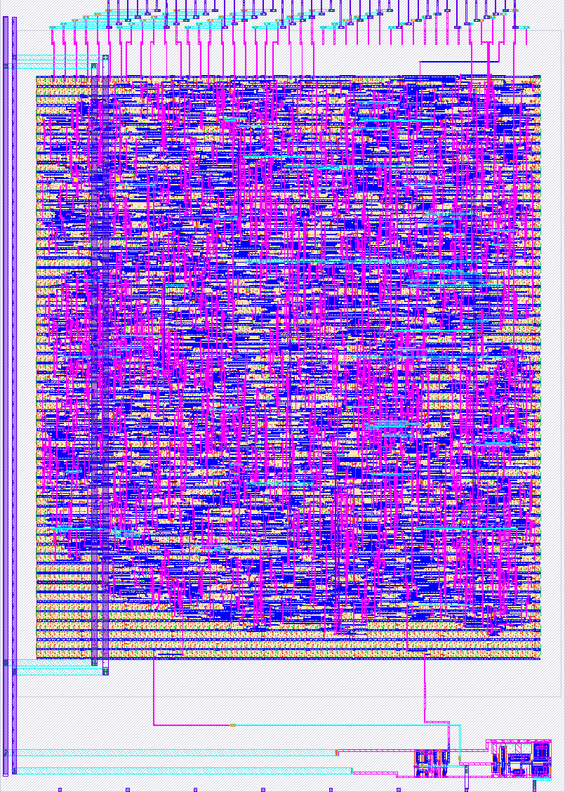
- Author: Priyabrata Dash
- Description: 8b/10b SERDES loopback: PRBS BIST, 3x-oversampling CDR, custom analog driver out ua[0], Schmitt slicer in ua[1]
- GitHub repository
- Open in 3D viewer
- Open in Tiny Tapeout Explorer
- Clock: 66500000 Hz
How it works
A complete UCIe-inspired serial link — transmitter, channel driver, receiver front-end, and clock recovery — in one 1x2 tile, with a built-in self test so the chip can prove itself with three switches and four LEDs.
Digital core (hardened macro: 1582 logic cells, 246 flip-flops, 155 x 190 um at 76.6% utilization): a PRBS-7 generator feeds an 8b/10b encoder and a 10:1 serializer to produce a 22.2 Mbps serial stream. On the receive side, a 3x-oversampling elastic CDR recovers the bit clock (tolerant to ±2000 ppm frequency offset and 0.35 UI jitter), a word aligner finds 8b/10b comma symbols, a 1:10 deserializer and decoder restore bytes, and a PRBS-7 checker counts errors. All timing derives from one 66.5 MHz input clock divided into a ratio-locked 1:3:30 family (sample / bit / parallel-word clocks), so the whole link runs from a single oscillator. The link is self-training: while the receiver is un-aligned the transmitter sends K28.5 comma idles; once alignment locks, PRBS data flows automatically, and if lock is ever lost the training idles resume on their own.
Analog cells (full-custom, hand-drawn): the serial stream leaves the chip through a 4-stage tapered CMOS pad driver on ua[0] (post-layout: 1.66 ns rise, 1.03 ns fall into 5 pF, 93 uA average at speed) and re-enters through a Schmitt-trigger slicer on ua[1] (post-layout thresholds VT+ = 1.215 V, VT- = 0.594 V — 0.62 V of hysteresis armor against channel noise, with 187/210 ps propagation delay). Both cells were verified through four generations of representation — hand analysis, schematic capture, LVS-matched layout, and parasitic-extracted simulation — with thresholds agreeing within millivolts across all four.
How to test
Clock the design at 66.5 MHz (the demo board's RP2040 can generate this) and release reset. Then:
-
Digital-only smoke test (no wiring needed): set ui[2:0] = 111 (PRBS generator on, checker on, internal digital loopback). Within milliseconds uo[0] (aligned), uo[1] (CDR locked) and uo[2] (PRBS sync) go high, the heartbeat on uo[3] blinks at ~2 Hz, and the 12-bit error counter on uo[7:4] + uio[7:0] stays at zero.
-
Full analog loopback: connect ua[0] to ua[1] through a series resistor (~50 Ω) on the breakout. Set ui[2:0] = 011 (loopback bit LOW so the serial stream routes through the analog pins). The link self-trains: comma idles stream from the driver, the slicer squares them up, the CDR locks, the aligner finds the commas, and PRBS traffic starts — same three lock LEDs up, error counter frozen at zero, now through real analog silicon.
-
Failure demo (the fun one): pull the loop wire. Alignment and sync drop, the error counter runs, and the transmitter automatically falls back to training idles. Reconnect the wire and watch the link heal itself.
External hardware
One jumper wire and one ~50 Ω series resistor from ua[0] to ua[1] on the analog breakout (test 2). Optionally an oscilloscope on ua[0] to see the 22.2 Mbps 8b/10b eye — edges are ~1-1.7 ns into 5 pF. Nothing else: the self-test is entirely on-chip.
Measured characteristics (pre-silicon, parasitic-extracted, tt 27C)
| TX driver (into 5 pF) | value |
|---|---|
| rise time (10-90%) | 1.66 ns |
| fall time (10-90%) | 1.03 ns |
| prop delay (rise/fall) | 1.00 / 0.81 ns |
| average supply current | 93.5 uA |
| RX slicer (Schmitt + buffer) | value |
|---|---|
| VT+ | 1.215 V |
| VT- | 0.594 V |
| hysteresis | 0.621 V |
| prop delay (rise/fall) | 187 / 210 ps |
| Link | value |
|---|---|
| line rate | 22.2 Mbps (66.5 MHz / 3) |
| coding | 8b/10b, PRBS-7 BIST |
| CDR tolerance | ±2000 ppm, 0.35 UI jitter |
| digital timing | 0 violations, 9 corners (setup slack +2.9 ns ss) |
IO
| # | Input | Output | Bidirectional |
|---|---|---|---|
| 0 | prbs_gen_en (1=transmit PRBS self-test pattern) | rx_aligned (word aligner locked) | prbs_err_cnt[4] (output) |
| 1 | prbs_chk_en (1=enable RX PRBS checker) | cdr_locked (clock recovery locked) | prbs_err_cnt[5] (output) |
| 2 | dig_loopback (1=internal digital loopback, bypass analog) | prbs_sync (checker synchronized) | prbs_err_cnt[6] (output) |
| 3 | heartbeat (~2.1 Hz blink) | prbs_err_cnt[7] (output) | |
| 4 | prbs_err_cnt[0] | prbs_err_cnt[8] (output) | |
| 5 | prbs_err_cnt[1] | prbs_err_cnt[9] (output) | |
| 6 | prbs_err_cnt[2] | prbs_err_cnt[10] (output) | |
| 7 | prbs_err_cnt[3] | prbs_err_cnt[11] (output) |
Analog pins
ua | PCB Pin | Internal index | Description |
|---|---|---|---|
| 0 | Q | 11 | TX driver output (22.2 Mbps serial, drive to ua[1] via ~50R) |
| 1 | X | 6 | RX slicer input (Schmitt trigger, 0.62 V hysteresis) |