140 TinyMind SoC
140 : TinyMind SoC
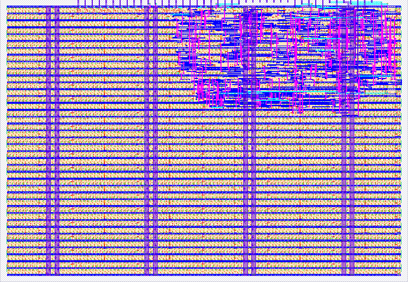
- Author: Sishi
- Description: A tiny processor-controlled 8-input, 3-class fixed-weight inference accelerator with a custom CPU, program ROM, clocked TinyMind core, confidence logic, and seven-segment output.
- GitHub repository
- Open in 3D viewer
- Open in Tiny Tapeout Explorer
- Clock: 10000000 Hz
TinyMind SoC
TinyMind SoC is a small educational processor-controlled inference accelerator implemented in Verilog for TinyTapeout.
The project demonstrates how a simple inference algorithm can evolve into a clocked digital system containing:
- a tiny custom CPU
- a program counter
- a small program ROM
- CPU registers
- a clocked TinyMind accelerator
- START/BUSY/DONE control
- result registers
- confidence calculation
- a seven-segment output interface
The design runs at 10 MHz.
The purpose of TinyMind is educational: to make it possible to follow a computation from a simple mathematical equation through RTL, registers, clock cycles, processor control, synthesis, standard cells, physical implementation, and ultimately GDS.
How it works
1. High-Level Architecture
The final TinyMind design is organized as a small System-on-Chip:
                     10 MHz CLOCK
                          │
                          ▼
                  ┌───────────────┐
                  │   Tiny CPU    │
                  │               │
ui_in[7:0] ──────►│ Program       │
                  │ Counter       │
                  │               │
                  │ ACC Register  │
                  │               │
                  │ Program ROM   │
                  └───────┬───────┘
                          │
                          ▼
                  ┌───────────────┐
                  │   TinyMind    │
                  │  Accelerator  │
                  │               │
                  │ Feature Reg   │
                  │               │
                  │ Score Logic   │
                  │               │
                  │ Winner Logic  │
                  │               │
                  │ Result Regs   │
                  └───────┬───────┘
                          │
                          ▼
                  ┌───────────────┐
                  │  CPU Result   │
                  │   Registers   │
                  └───────┬───────┘
                          │
                          ▼
                  ┌───────────────┐
                  │ Seven-Segment │
                  │    Decoder    │
                  └───────┬───────┘
                          │
                          ▼
                     uo_out[7:0]
The CPU controls the TinyMind accelerator.
The accelerator performs the inference calculation.
The CPU captures the result and makes it available to the seven-segment display.
2. Input Features
TinyMind receives eight binary input features through:
ui_in[7:0]
Each bit represents a yes/no answer:
0 = No
1 = Yes
The features are:
| Input | Meaning |
|---|---|
ui_in[0] |
Likes mathematics |
ui_in[1] |
Likes programming |
ui_in[2] |
Likes electronics |
ui_in[3] |
Likes physics |
ui_in[4] |
Likes data and patterns |
ui_in[5] |
Likes building things |
ui_in[6] |
Likes design and creativity |
ui_in[7] |
Likes experimentation and research |
For example:
ui_in = 10100101
represents one particular combination of the eight features.
3. Tiny CPU
The SoC contains a deliberately small custom CPU/controller.
The CPU includes:
Program Counter
      +
8-bit ACC Register
      +
Result Registers
      +
Control Logic
      +
Program ROM
This CPU is intentionally simple.
It is not RISC-V and does not implement a standard instruction-set architecture.
Instead, it demonstrates the fundamental processor concept:
Program Counter
      │
      ▼
Instruction
      │
      ▼
Execute Operation
      │
      ▼
Update State
      │
      ▼
Next Instruction
4. Program Counter
The Program Counter, or PC, keeps track of which instruction the CPU is currently executing.
Conceptually:
PC = 0
  ↓
WAIT_RUN

clock ↑

PC = 1
  ↓
READ_INPUT

clock ↑

PC = 2
  ↓
WRITE_FEATURE

clock ↑

PC = 3
  ↓
START
The PC is sequential state and is therefore implemented using flip-flops after synthesis.
5. Program ROM
The CPU executes a fixed eight-step program.
| PC | Instruction | Operation |
|---|---|---|
| 0 | WAIT_RUN |
Wait for run enable |
| 1 | READ_INPUT |
Capture the external feature vector |
| 2 | WRITE_FEATURE |
Write the feature vector to TinyMind |
| 3 | START |
Start the TinyMind accelerator |
| 4 | WAIT_DONE |
Wait for inference to finish |
| 5 | READ_RESULT |
Capture the accelerator result |
| 6 | DISPLAY |
Present the captured result |
| 7 | LOOP |
Return for another inference |
The program flow is:
WAIT_RUN
    │
    ▼
READ_INPUT
    │
    ▼
WRITE_FEATURE
    │
    ▼
START
    │
    ▼
WAIT_DONE
    │
    ▼
READ_RESULT
    │
    ▼
DISPLAY
    │
    ▼
LOOP
    │
    └──────────────► READ_INPUT
Because this program is extremely small, the Verilog description does not require a large physical memory.
Synthesis can implement the instruction-selection logic using ordinary combinational standard cells.
6. CPU Accumulator
The CPU contains an 8-bit register called acc.
During READ_INPUT, the CPU captures:
ui_in[7:0]
into:
acc[7:0]
Conceptually:
ui_in = 10100101
        │
        │ READ_INPUT
        │ clock ↑
        ▼
┌─────────────────┐
│ ACC = 10100101  │
└─────────────────┘
The accumulator allows the CPU to remember the feature vector while it performs later instructions.
7. Writing the TinyMind Feature Register
During the WRITE_FEATURE instruction, the CPU presents the contents of the accumulator to the TinyMind accelerator.
CPU ACC
   │
   ▼
feature_data
   │
   ▼
TinyMind Feature Register
The CPU generates a one-cycle feature_write signal.
On the corresponding clock edge, TinyMind captures the eight feature bits.
The design now contains state on both sides:
CPU Register
     │
     ▼
TinyMind Register
8. Starting the Accelerator
During the START instruction, the CPU generates a one-cycle start signal.
Conceptually:
CPU
 │
 │ START
 ▼
TinyMind
TinyMind responds by asserting:
BUSY = 1
DONE = 0
The CPU then reaches the WAIT_DONE instruction.
9. TinyMind Inference
TinyMind evaluates three fixed-weight scoring functions.
AI-oriented score
score_ai =
x0 + x1 + x4 - x5 + x7 + 1
Hardware-oriented score
score_hardware =
x0 + x2 + x3 + x5 - x6
Creative-oriented score
score_creative =
-x1 - x2 + x5 + x6 + x7 + 1
Conceptually, the three score paths operate in parallel:
                Feature Register
                       │
           ┌───────────┼───────────┐
           │           │           │
           ▼           ▼           ▼
       AI Score    Hardware     Creative
                    Score        Score
           │           │           │
           └───────────┼───────────┘
                       │
                       ▼
                 Winner Logic
This is one of the important differences between thinking about an algorithm as software and implementing it directly as hardware.
The three score expressions are represented by combinational logic rather than being executed one after another by the TinyMind accelerator.
10. Winner Selection
After calculating the three scores, TinyMind determines which score is largest.
The internal class encoding is:
00 = AI-oriented
01 = Hardware-oriented
10 = Creative-oriented
Tie priority is:
AI > Hardware > Creative
For example:
AI       = 4
Hardware = 2
Creative = 3

Winner = AI
11. Confidence
TinyMind also identifies the second-highest score.
Confidence is calculated as:
confidence =
winning score - second-highest score
For example:
AI       = 5
Hardware = 2
Creative = 3
Therefore:
winning score = 5
second score  = 3

confidence = 5 - 3 = 2
The stored confidence value is limited to a maximum value of 9.
12. Close Prediction
TinyMind also generates a close_prediction result.
It is asserted when:
confidence margin <= 1
For example:
AI       = 4
Hardware = 3
Creative = 1
The margin is:
4 - 3 = 1
Therefore:
close_prediction = 1
This signal is ultimately connected to the decimal-point output.
13. Result Registers
The TinyMind accelerator stores:
result_class
confidence
close_prediction
in clocked registers.
The fundamental accelerator datapath is therefore:
FEATURE REGISTER
       │
       ▼
COMBINATIONAL
INFERENCE LOGIC
       │
       ▼
RESULT REGISTERS
This is the classic synchronous digital structure:
REGISTER
   ↓
LOGIC
   ↓
REGISTER
14. BUSY and DONE
The CPU and accelerator communicate using a simple handshake.
CPU
 │
 │ START
 ▼
TinyMind
 │
 ├── BUSY = 1
 │
 │   inference
 │
 └── DONE = 1
        │
        ▼
       CPU
The sequence is:
START
  │
  ▼
BUSY
  │
  ▼
COMPUTE
  │
  ▼
DONE
The CPU remains at WAIT_DONE until the accelerator indicates that the result is available.
15. CPU Reads the Result
Once DONE is detected, the CPU moves to READ_RESULT.
The CPU captures:
result_class
confidence
close_prediction
into its own result registers.
The complete register movement is therefore:
External Inputs
      │
      ▼
CPU ACC Register
      │
      ▼
TinyMind Feature Register
      │
      ▼
Inference Logic
      │
      ▼
TinyMind Result Registers
      │
      ▼
CPU Result Registers
      │
      ▼
Display
16. Seven-Segment Display
The final class is converted into a seven-segment pattern.
The display shows:
A = AI-oriented

H = Hardware-oriented

C = Creative-oriented
The seven segment outputs use:
uo_out[6:0]
The segment mapping is:
| Output | Segment |
|---|---|
uo_out[0] |
g |
uo_out[1] |
f |
uo_out[2] |
e |
uo_out[3] |
d |
uo_out[4] |
c |
uo_out[5] |
b |
uo_out[6] |
a |
The class patterns are:
A = 1110111
H = 0110111
C = 1001110
The close-prediction signal is:
uo_out[7]
and can be used as the decimal point.
17. Clocking
The design runs at:
10 MHz
A 10 MHz clock has a period of:
100 ns
Registers capture their inputs on rising clock edges.
A simplified register-to-register timing path looks like:
Rising Edge                           Rising Edge
     │                                    │
     ▼                                    ▼
┌──────────┐                        ┌──────────┐
│ Register │                        │ Register │
│ captures │                        │ captures │
└────┬─────┘                        └──────────┘
     │
     │
     ▼
 Combinational
     Logic
     │
     ▼
 Next Value
     │
     │
     └──────────────────────────────►

     <----------- 100 ns ----------->
Static timing analysis checks whether the combinational path can complete in the available clock period while accounting for the relevant timing requirements.
How to test
Step 1 — Start the Clock
Provide the system clock on:
clk
The target operating frequency is:
10 MHz
Step 2 — Reset the SoC
The reset is active-low.
Assert reset:
rst_n = 0
Then release it:
rst_n = 1
After reset, the CPU begins at program address 0:
WAIT_RUN
Step 3 — Set the Input Features
Place the eight binary feature values on:
ui_in[7:0]
For example:
ui_in = 10100101
Step 4 — Enable CPU Execution
Set:
uio_in[0] = 1
This is the CPU run-enable signal.
The CPU now begins processing the feature vector.
Step 5 — CPU Executes the Program
The CPU automatically performs:
READ_INPUT
    │
    ▼
WRITE_FEATURE
    │
    ▼
START
    │
    ▼
WAIT_DONE
    │
    ▼
READ_RESULT
    │
    ▼
DISPLAY
No external controller needs to directly manipulate the internal TinyMind accelerator signals.
Step 6 — Observe the Output
Read:
uo_out[6:0]
The output represents:
A
H
or
C
depending on the predicted class.
Read:
uo_out[7]
for the close-prediction indicator.
If:
uo_out[7] = 1
the winning and second-place scores were separated by a margin of 1 or less.
Step 7 — Process Another Input
While:
uio_in[0] = 1
the CPU loops and processes input vectors repeatedly.
Conceptually:
READ
 ↓
RUN TINYMIND
 ↓
DISPLAY
 ↓
LOOP
 ↓
READ AGAIN
If the input switches change, the CPU can capture the new feature vector during a later loop iteration.
Setting:
uio_in[0] = 0
causes the CPU to return to its wait state rather than continuing normal inference loops.
Automated Verification
The project includes a cocotb testbench.
There are eight binary input features.
Therefore the total number of possible feature vectors is:
2^8 = 256
The testbench exhaustively tests all 256 combinations.
For each combination, Python independently calculates:
AI score
Hardware score
Creative score
Winner
Confidence
Close prediction
The SoC is then allowed to process the same input.
The test compares the external seven-segment output against the Python reference model.
Conceptually:
                 Feature Vector
                  /          \
                 /            \
                ▼              ▼
        Python Model       TinyMind SoC
                │              │
                ▼              ▼
        Expected Result     Actual Result
                │              │
                └──────┬───────┘
                       ▼
                    COMPARE
This means the verification checks the complete SoC path:
INPUT
  ↓
CPU
  ↓
ACC REGISTER
  ↓
TINYMIND
  ↓
RESULT
  ↓
CPU
  ↓
DISPLAY
  ↓
OUTPUT
rather than directly controlling only the inference logic.
Pinout Summary
Dedicated Inputs
| Pin | Function |
|---|---|
ui_in[0] |
Likes mathematics |
ui_in[1] |
Likes programming |
ui_in[2] |
Likes electronics |
ui_in[3] |
Likes physics |
ui_in[4] |
Likes data and patterns |
ui_in[5] |
Likes building things |
ui_in[6] |
Likes design and creativity |
ui_in[7] |
Likes experimentation and research |
Bidirectional Pins Used as Inputs
| Pin | Function |
|---|---|
uio_in[0] |
CPU run enable |
uio_in[1] |
Unused |
uio_in[2] |
Unused |
uio_in[3] |
Unused |
uio_in[4] |
Unused |
uio_in[5] |
Unused |
uio_in[6] |
Unused |
uio_in[7] |
Unused |
The bidirectional pins are never driven by the design:
uio_out = 00000000
uio_oe  = 00000000
Dedicated Outputs
| Pin | Function |
|---|---|
uo_out[0] |
Seven-segment g |
uo_out[1] |
Seven-segment f |
uo_out[2] |
Seven-segment e |
uo_out[3] |
Seven-segment d |
uo_out[4] |
Seven-segment c |
uo_out[5] |
Seven-segment b |
uo_out[6] |
Seven-segment a |
uo_out[7] |
Close-prediction / decimal point |
External hardware
No external hardware is required for RTL or gate-level simulation.
For a physical TinyTapeout demonstration, the design needs access to:
8 feature inputs
1 CPU run-enable input
clock
reset
7-segment outputs
The conceptual physical demonstration is:
Feature switches
      │
      ▼
 ui_in[7:0]
      │
      ▼
 TinyMind SoC
      │
      ▼
CPU executes program
      │
      ▼
TinyMind inference
      │
      ▼
uo_out[7:0]
      │
      ▼
7-Segment Display

A / H / C
The exact procedure for setting inputs, clocking the design, and connecting the output depends on the TinyTapeout demo board/controller being used.
What this project demonstrates
TinyMind is intentionally small enough that the complete hardware stack can be studied.
The project demonstrates the progression:
Mathematical Equation
        │
        ▼
Combinational Logic
        │
        ▼
Clocked Logic
        │
        ▼
Registers
        │
        ▼
Accelerator
        │
        ▼
START / BUSY / DONE
        │
        ▼
Tiny CPU
        │
        ▼
Program Counter
        │
        ▼
Program ROM
        │
        ▼
Processor-Controlled Accelerator
        │
        ▼
Synthesis
        │
        ▼
Standard Cells
        │
        ▼
Physical Design
        │
        ▼
GDS
TinyMind is not intended to be a high-performance AI accelerator or general-purpose processor.
It is a small fixed-weight neural-style inference accelerator used to demonstrate how computation can be transformed into clocked digital hardware and integrated into a small processor-controlled system.
IO
| # | Input | Output | Bidirectional |
|---|---|---|---|
| 0 | Feature 0 - likes mathematics | Seven-segment g | CPU run enable |
| 1 | Feature 1 - likes programming | Seven-segment f | Unused |
| 2 | Feature 2 - likes electronics | Seven-segment e | Unused |
| 3 | Feature 3 - likes physics | Seven-segment d | Unused |
| 4 | Feature 4 - likes data and patterns | Seven-segment c | Unused |
| 5 | Feature 5 - likes building things | Seven-segment b | Unused |
| 6 | Feature 6 - likes design and creativity | Seven-segment a | Unused |
| 7 | Feature 7 - likes experimentation and research | Close-prediction decimal point | Unused |