943 Tiny Snake with PRISM 8
943 : Tiny Snake with PRISM 8
- Author: Ken Pettit
- Description: A tiny snake on the 7-Segment LED, plus an 8-State FSM
- GitHub repository
- Open in 3D viewer
- Open in Tiny Tapeout Explorer
- View in Wokwi
- Clock: 10000 Hz
How it works
This is a very simple Wokwi example that incorporaates two different designs.
Design 1 - 7-Seg Snake
The first design uses the 7-Segment display to show a 3-segment "snake" as it moves around the display. It uses three 3-bit registers to store the current location of the "head", "body" and "tail", along with a register identifying the direction (0=clockwise, 1=counter clockwise).
There are two larger registers also, one a simple counter for speed control and the other a Linear Feedback Shift Register (LFSR) to randomize the direction of travel.
Design 2 - Mini PRISM
The second design is a small implementation of the Programmable Reconfigurable Indexed State Machine (PRISM). This is a Verilog programmable 8-state finite state machine that uses an 8-entry, 22 wide State Table Execution Word (STEW) to define state transitions and output values based on current state and input values. The PRISM includes a counter
How to test
Supply a 10 KHz clock. Then set the speed using the ui_in[7:0] pins. Larger binary values represent slower speed. Start off with something like 8'h20 (i.e. ui_in[5] HIGH, the rest LOW). Watch the snake move around. Try different speeds.
NOTE: When changing from a slower to a faster speed, the initial update may take a few seconds. This is because the This is because the counter may already be larger than the newly entered "speed" value, and therefore must count all the way up until it wraps to zero. The speed compare is a simple EQUAL circuit and doesn't check for GREATER-THAN-OR-EQUAL.
External hardware
Only need the 7-Segment display on the demo board.
PRISM
PRISM (Programmable Reconfigurable Indexed State Machine) is a block that executes a Verilog-coded Mealy state machine loaded via a runtime loadable configuration bitstream generated by a custom branch of Yosys. PRISM includes it's own counter and compare sub-peripheral for performing timing operation as well.
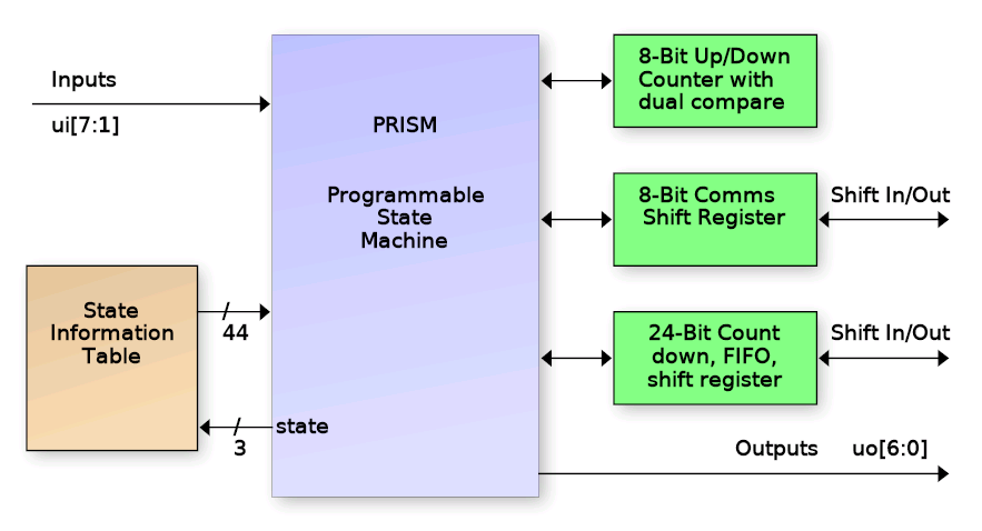
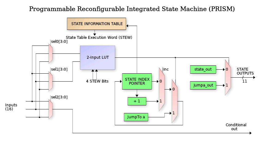
The PRISM controller block is a programmable state machine that uses an N-bit (3 in this case) index register to track the current FSM state. That index is a pointer into the State Information Table (SIT) to request the State Execution Word (STEW).
What can it do?
Operating priciples of PRISM
PRISM supports FSM designs up to 8 states and includes controllable peripherals such as counters, communication shift register, FIFO and interrupt support. It also features an integrated debugger with 2 breakpoints, single-stepping and readback of state information. Due to long combinatorial delays, PRISM operates from a divide-by-two clock (32Mhz max). The following is a block diagram of the PRISM controller:
Each state is encoded with a 22-bit execution word that controls the FSM output values, input values and state transition decision tree for that state. The peripheral is operated by loading a "Chroma" (more on that below), or execution personality in the 192 bit configuration array as well as configuring the 3 bits of operational mode configurtaion. The 3-bits of operational configuration include:
- Debug output bit: Sends internal state operations to uo_out[7:0]
- Auto-clear bit: Auto clears the counter when compare match occurs
- Split-coiunter: Splits the 15-bit conter into an 8-bit plus 7-bit each with individual compare.
Once a chroma has been loaded, the control register programmed and the PRISM enabled, the FSM will start at state 0. Eight of the bits in the State Execution Word (STEW) specify which of 16 inputs get routed to the 2-input Look Up Table (LUT) that makes the decision for jumping to the specified state (stored in 3 bits of the STEW). While in any state, there is a set of 11 (from the STEW) output bits that drive the PRISM block outputs when the LUT output is zero (no jump) and 11 more that are output during a jump (transitional outputs).
Each state also has an independent 16-input mux (4-bits from STEW) driving a 1-input LUT to drive a "conditional output". This is an output who's value is not strictly depedent on the static values in the STEW for the current state, but rather depends on the selected input during that state.
State Looping (important)
In larger PRISM implementations, each state has "dual-compare" with two N-bit LUTs which allows jumping to one of two possible states. Due to size restrictions, this peripheral does not include dual-compare. Instead the PRISM implementation has (in each state's STEW), a single "increment state" bit.
In any state where the 'inc' bit is set and the LUT output is FALSE (i.e no jump), then the state will increment to the next state, and the "starting state" of the first occurance of this will be saved (i.e. start of loop). Then each successive state can test a different set of inputs to jump to different states. When a state is encountered with the 'inc' bit NOT set, PRISM will loop back to the "starting state" and loop through that set of states until the first TRUE from a LUT causing a jump, clearing the loop.
TL/DR
- Load a Chroma defining the FSM and enable PRISM.
- State starts at zero.
- Each state chooses up to 3 of 16 inputs via config bits.
- 2-input LUT decides if "jump to defined state" occurs.
- Increment bit decides if "state looping" is in effect.
- State looping ends when first LUT jump occurs.
- Outputs bits from STEW for "non-jump" and "transitional jump".
- One conditional output based on single selected input per state.
External PRISM Inputs
Inputs to the PRISM engine come from the uio_in[2:0] pins of the TinyTapeout ASIC Outpus are presented on uio_out[7:3].
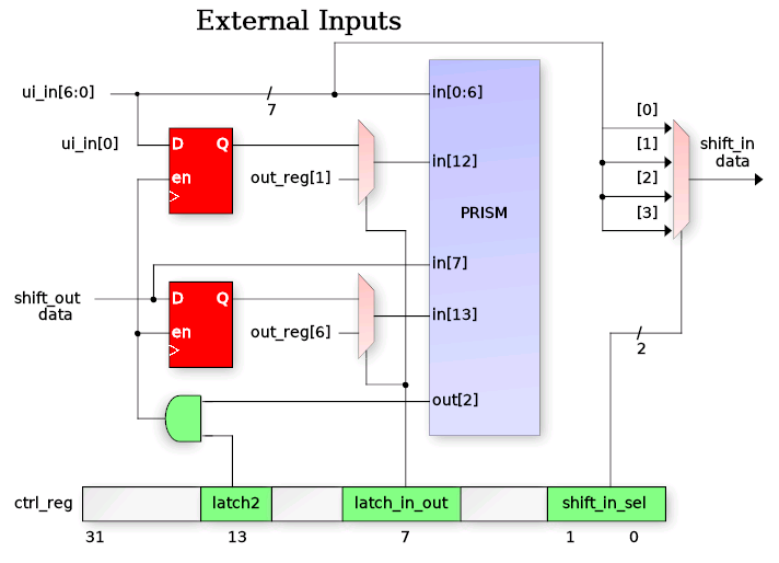
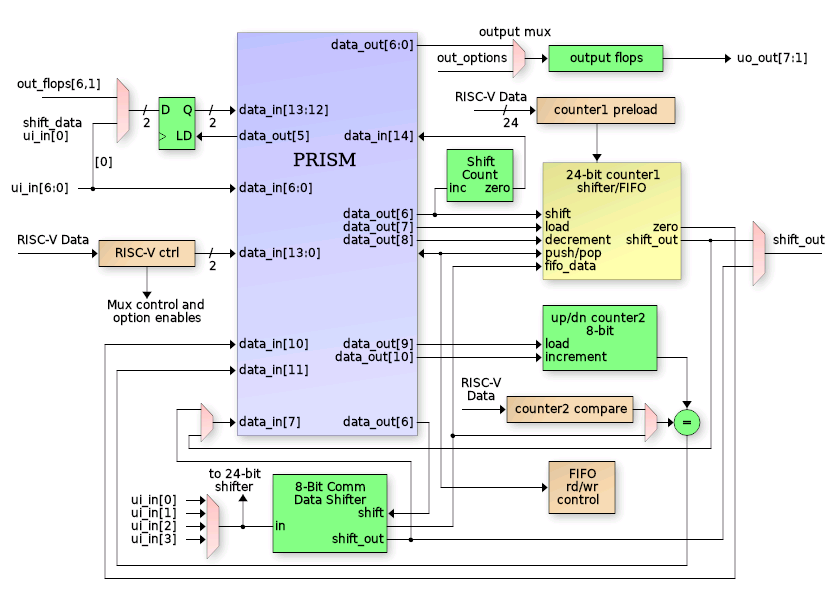
In addition to direct input to the PRISM, a few inputs also have special functions (refer to the diagram below for visual). Input ui_in[0] can be programmatically latched by the chroma using PRISM out[2] when configured via the ctrl_reg latch2 and latch_in_out bits. The latched input version becomes available on PRISM input in[12]. This allows for detection of rising or falling edges.
Additionally any one of inputs in[3:0] can be used as shift register "shift_in_data" to feed the 8-bit and 24-bit shift registers. Selection of which pin of in[3:0] is made using ctrl_reg field "shift_in_sel".
The diagram also shows that shift_out_data can be latched via the out[5] signal. It is to allow protocols like SPI to present serial output data on one edge while shifting occurs on the opposite edge (by selecting in[13] as the controlling input for the cond_out[0] conditional output.
The in[13:12] inputs to PRISM can also be driven by the registered version of out[6] and out[1] bits. This allows a chroma to use a single FSM state to perform multiple output operations using the in-state vs. transitional outputs. For instance, the shift_en signal is output on out[6]. The following code will perform a rising plus falling shift edge in a single FSM state since a registered version of the shift_en is used to detect when to transition to the next state.
STATE_SHIFT_BITS:
   begin
      // Shift the next bit out
      shift_en = 1'b1;

      // Detect the rising shift_en bit to go to next state
      if (shift_en_in)
      begin
         next_state = STATE_DELAY;
         shift_en = 1'b0;
      end
   end
External PRISM Outputs
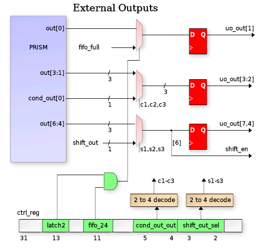
The PRISM has 5 outputs, all of which are visible on uio_out[7:3]. Outputs [5] and [4] also have special internal functions as follows:
out[5]: Counter increment out[4]: Counter clear (when not in auto-clear mode)
All outputs are registered via the main clock to prevent output glitching caused by combinatoril transitions during state decision switching.
15-Bit Counter
The 8-bit counter is an up/down/clear counter controllable from the PRISM chroma. There are three PRISM outputs plus a ctrl_reg bit that contols the operation (see figure below). Upon reset (or disabling PRISM) the count will be zero. In any PRISM state, the counter can be cleared, incremented or decremented (assuming decrement has been enabled via the count2_dec ctrl_reg bit). The decrement is provided as a configurable feature in case it is not needed but uo_out[6] is needed (since they share the same out[5] signal).
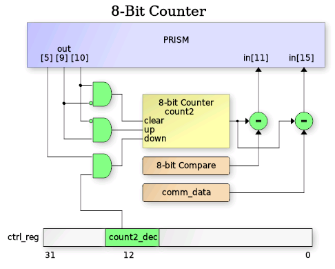
The current 8-bit count2 value is compared against both the 8-bit count2_compare register (fixed register accessible by TinyQV with R/W access) and the comm_data register (also R/W accessible). The result of each of these compares are made available on PRISM inputs in[11] and in[15]. A running chroma can use these compare inputs for timing, terminal count checking, etc.
Chroma
Chroma are PRISM's version of "personalities". Each chroma is a unique hue of PRISM's spectrum of behavior. Chroma's are coded as Mealy state machines in Verilog to define FSM inputs, outputs and state transitions:
always @(posedge clk or negedge rst_n)
   if (~rst_n)
      curr_state <= 3'h0;
   else
      curr_state <= fsm_enable ? next_state : 'h0;

always_comb
begin
   pin_out[5:0]   = 6'h0;
   count1_dec     = 1'b0;
   etc.

   case (curr_state)
   STATE_IDLE:       // State 0
      begin
         // Detect I/O shift start
         if (host_in[HOST_START])
         begin
            // Load inputs
            pin_out[GPIO_LOAD] = 1'b0;

            // Load 24-bit shift register from preload (our OUTPUTS)
            count1_load = 1'b1;
            next_state = STATE_LATCH_INPUTS;
         end
      end
   STATE_LATCH_INPUTS:  // State 1
      begin
         next_state = STATE_SHIFT_BITS;
      end
   etc.
end
Chroma are compiled into PRISM programmable bitstreams via a custom fork of Yosys (see link below) using a configuration file describing the architecture in the TinyQV PRISM peripheral. In addition to bitstream generation, the Yosys PRISM backend also calculates the ctrl_reg value for configuring the PRISM peripheral muxes, etc. There are several output formats including C, Python and columnar list:
| ST | Mux0 | Mux1 | Mux2 | Inc | JmpA | OutA | Out | CfgA | CfgB | STEW |
|---|---|---|---|---|---|---|---|---|---|---|
| 0 | 8 | 0 | 0 | 0 | 1 | 100 | 001 | a | 0 | 28800012010 |
| 1 | 0 | 0 | 0 | 0 | 2 | 001 | 000 | f | 0 | 3c008004000 |
| 2 | d | 0 | 0 | 0 | 3 | 001 | 041 | a | 0 | 2800841601a |
| 3 | e | 0 | 0 | 1 | 2 | 001 | 001 | 5 | 0 | 1400801401d |
| 4 | 0 | 0 | 9 | 0 | 5 | 001 | 000 | f | 2 | bc00800b200 |
| 5 | 8 | 0 | 0 | 0 | 0 | 001 | 001 | 5 | 0 | 14008010010 |
| 6 | 0 | 0 | 0 | 0 | 0 | 001 | 000 | f | 0 | 3c008000000 |
| 7 | 0 | 0 | 0 | 0 | 0 | 001 | 000 | f | 0 | 3c008000000 |
The table has the following fields
- ST: the state (obvious)
- Mux0: Selects input for LUT2 input 0 (jump decision)
- Mux1: Selects input for LUT2 input 1
- Mux2: Selects input for LUT1 Conditional Output
- Inc: Set when next state looping is requested (i.e. 'else state <= ST_A')
- JmpA: The "Jump to" state if LUT2 output is TRUE
- OutA: Outputs during "jump to" JmpA state (LSB is PRISM out[0])
- Out: Output during no-jump, steady-state dwelling
- CfgA: The LUT2 4-bit lookup table values
- CfgB: The LUT1 2-bit lookup table values
- STEW: The complete word aggregrated in proper bit order
IO
| # | Input | Output | Bidirectional |
|---|---|---|---|
| 0 | speed[0]/prism_enable | seg_a | prism_in[0] |
| 1 | speed[1]/prism_cfg_data | seg_b | prism_in[1] |
| 2 | speed[2] | seg_c | prism_in[2] |
| 3 | speed[3] | seg_d | prism_out[0] |
| 4 | speed[4] | seg_e | prism_out[1] |
| 5 | speed[5] | seg_f | prism_out[2] |
| 6 | speed[6] | seg_g | prism_out[3] |
| 7 | speed[7] | prism_debug | prism_cfg_clk |